MIM Process Options
MIM Molding
Molding converts the feedstock into a defined shape. The feedstock granules are loaded into the hopper of the molding machine as shown here. It is essentially the same presses used for plastic injection molding. MIM and CIM feedstocks are more abrasive than most plastics, so specialized screws and barrels are typically used for powder injection molding. For high production components, a robot system is used for handling and staging for de-binding and sintering.
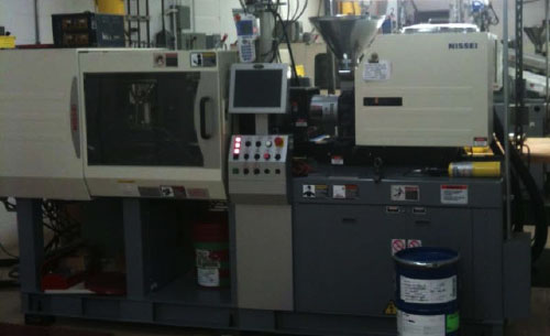
The molder conveys the feedstock pellets into a heated barrel with an internal screw for mixing, compressing, and melting the feedstock. A nozzle at the end of the barrel seats up against the mold during filling. The mold is clamped closed. It is important for the screw to heat, melt, and mix the feedstock to ensure homogeneity and no trapped air bubbles. The screw has a taper that compresses the hot feedstock to squeeze out any trapped air.
When ready to fill the mold, the hot feedstock is injected into the mold cavity. In molding, the feedstock flows to fill out the cavity. Once the mold cavity is filled, the feedstock is cooled to freeze the powder-binder mixture into the desired shape. When sufficiently cool, the rigid component is ejected from the mold and the molding cycle repeated, typically once every fifteen to forty-five seconds.
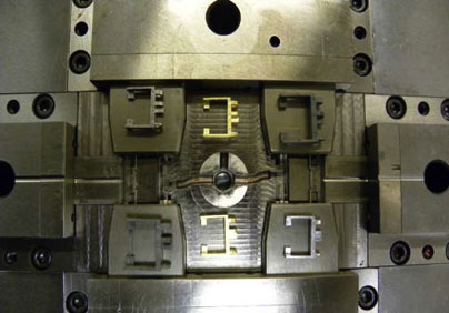
Two Cavity mold with “Green” parts (upper right and lower left), Sintered parts (upper left and lower right), and Gold Plated finished parts (upper and lower center).
During molding, the molten feedstock flows into the cavity from the gate toward the vent, which allows air to escape from the mold as the feedstock is injected. Vent size and location is part of the tool design, an improperly designed tool will lead to trapped air pockets in the molded shape or flash on the parts if the vents are too large.
Molding temperatures depend on the binder melt temperature, but are often below about 200°C or 400°F. The mold is cooler than the feedstock, so the feedstock viscosity increases as it flows into the mold and gives up heat to the tooling. Cooling increases flow resistance so sophisticated molding relies on high pressures to rapidly fill the cavity. The peak molding pressure varies with the geometry, but might range from 1.4 MPa to 60 MPa (200 to 8,500 psi).
Multiple cavity molding is used to increase productivity, and up to 64-cavity molds are used in MIM production. Multiple cavity molding may present some balance and control issues; hence, the tradeoff between the molding issues, dimensional stability, tooling cost, and machine productivity often results in a compromise of single, two, or four-cavity molds to maintain tighter dimensional capability.